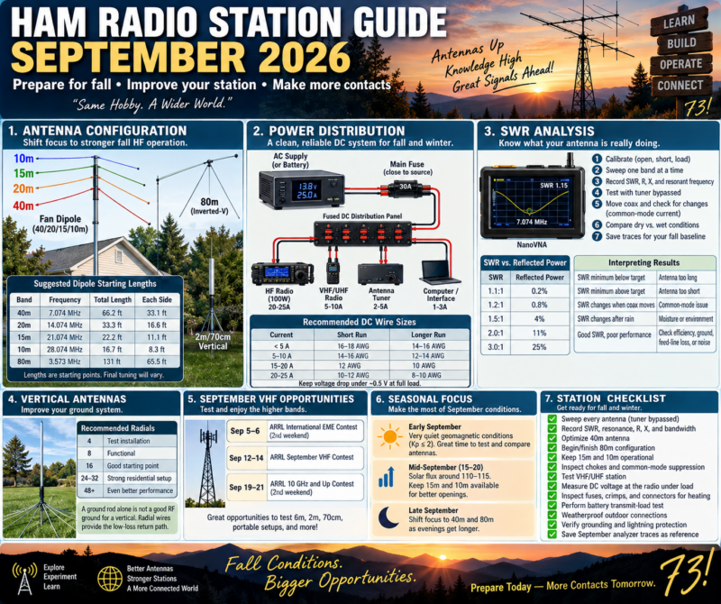
Monthly focus: shift the station toward stronger fall HF operation, prepare 40 and 80 meters for longer evenings, verify DC-power reliability before colder weather, and establish a clean SWR baseline after summer heat and thunderstorms.
September 2026 opens with unusually quiet space-weather conditions. NOAA’s September 1, 2026 three-day forecast expects Kp to remain at or below 2 through September 3, with no G1-or-greater geomagnetic storms expected and only a 10% daily chance of R1–R2 radio blackouts. NOAA’s September 1 longer-range forecast places the F10.7 solar flux mostly around 95–115 through much of September, with the stronger portion currently forecast around September 15–20.
That makes September a particularly useful month for comparing antennas under relatively stable conditions rather than assuming every signal change is caused by propagation.
1. September Antenna Configuration
The seasonal priority should begin moving away from a summer emphasis on 6 and 10 meters and toward 20, 40, and eventually 80 meters, while keeping the higher bands available whenever conditions support them.
| Band | September role | Recommended configuration |
|---|---|---|
| 80m | Evening/night regional work | Dipole, inverted-V, loaded dipole |
| 40m | Major evening/night band | Dipole, fan dipole, EFHW, vertical |
| 20m | Daytime and early-evening DX | Dipole, vertical, beam |
| 15m | Opportunistic daytime DX | Fan-dipole element or dedicated antenna |
| 10m | Check during stronger solar periods | Dipole, vertical, small beam |
| 6m | Less seasonal Es, but still useful | Horizontal dipole, Moxon, Yagi |
| 2m/70cm | Repeaters, local work, VHF contest | Vertical plus horizontal antenna if possible |
For a general-purpose September station, a very effective combination is a 40/20/15/10-meter fan dipole plus a separate 80-meter antenna. Trying to place every HF band on one compact fan structure often creates more interaction than it solves.
2. Prepare 40 Meters First
September is an excellent month to optimize 40 meters because darkness is arriving earlier and the band becomes increasingly useful during evening operating.
For a dipole centered near the FT8 frequency of 7.074 MHz, the standard 468/f starting formula gives approximately:
66.2 feet total, or about 33.1 feet per side.
For a more general SSB-oriented antenna centered near 7.200 MHz, the starting length is approximately 65 feet total.
These are construction starting points, not final dimensions. Wire insulation, height, nearby buildings, trees, gutters, attic materials, and element interaction can all shift resonance.
For an inverted-V, keep the feedpoint as high as practical and avoid extremely acute angles between the legs. The ends can be lower, but keep them away from people and conductive objects.
3. Begin 80-Meter Preparation
If you want improved fall and winter regional coverage, September is the month to begin 80-meter work rather than waiting until November.
At approximately 3.573 MHz, an FT8-centered half-wave dipole starts near 131 feet total. Many residential properties cannot accommodate that straight-line span, so practical alternatives include an inverted-V, bent dipole, loaded dipole, shortened antenna, or a carefully designed multiband system.
Do not judge an 80-meter antenna solely by SWR. A heavily shortened antenna can present an attractive 1.2:1 match while still suffering substantial loading-coil or ground loss.
For lower HF bands, efficiency and radiation resistance matter more than obtaining a perfect meter reading.
4. Keep 15 and 10 Meters Available
NOAA’s September 1 forecast has solar flux increasing from approximately 95–105 during the first half of September toward 110–115 around September 15–20, before easing toward the end of the month.
Do not dismantle your higher-band antennas yet.
During the stronger part of the forecast period, check:
| Band | Digital calling area to monitor |
|---|---|
| 20m FT8 | 14.074 MHz |
| 15m FT8 | 21.074 MHz |
| 10m FT8 | 28.074 MHz |
| 6m FT8 | 50.313 MHz |
Even when a band sounds silent on SSB, digital monitoring can reveal propagation that is not obvious by listening.
5. September Fan-Dipole Configuration
A useful three-band or four-band fan dipole can begin with these approximate dimensions:
| Band | Frequency | Total starting length | Each side |
|---|---|---|---|
| 40m | 7.074 MHz | 66.2 ft | 33.1 ft |
| 20m | 14.074 MHz | 33.3 ft | 16.6 ft |
| 15m | 21.074 MHz | 22.2 ft | 11.1 ft |
| 10m | 28.074 MHz | 16.7 ft | 8.3 ft |
Leave the wires slightly long.
Tune from the lowest-frequency element upward:
40m → 20m → 15m → 10m
After adjusting each higher-frequency element, sweep the lower bands again. Fan-dipole elements are electromagnetically coupled, so changing one wire can shift another.
Place a 1:1 current choke near the feedpoint. ARRL notes that dipoles and other complete antennas generally do not require an RF ground when common-mode feed-line currents are properly controlled; current or choke baluns are commonly used for this purpose. (ARRL)
6. September Vertical-Antenna Work
Late summer is a good opportunity to inspect a vertical before leaves, wet ground, frost, and winter weather complicate maintenance.
Do not use SWR as the sole measure of vertical performance. A lossy ground system can produce deceptively good SWR because ground resistance becomes part of the feedpoint resistance.
For a ground-mounted quarter-wave vertical, concentrate on repairing or expanding the radial field.
| Ground system | Practical interpretation |
|---|---|
| 4 radials | Test installation |
| 8 radials | Functional |
| 16 radials | Good practical starting point |
| 24–32 radials | Strong residential installation |
| 48+ radials | Increasingly serious ground system |
ARRL specifically notes that a ground rod by itself provides relatively high RF resistance for a quarter-wave vertical and that radial wires provide the lower-loss return path the antenna needs. (ARRL)
7. September VHF Opportunity
September is not exclusively an HF month.
The 2026 ARRL September VHF Contest runs from 1800 UTC September 12 through 0259 UTC September 14and uses authorized amateur frequencies above 50 MHz. It is an excellent reason to test 6 meters, 2 meters, 70 centimeters, grid-square logging, portable antennas, and horizontal polarization. (ARRL Contests)
ARRL also has its second International EME Contest weekend on September 5–6 and the second 10 GHz and Up weekend on September 19–21. (ARRL Contests)
Even without EME or microwave equipment, increased contest activity makes September a useful time to evaluate VHF receive performance.
8. Power Distribution: September Reliability Check
September should be the month when the station’s DC system receives a complete inspection before winter.
A clean station topology is:
AC supply or battery → main protection → fused DC distribution → separately fused equipment branches
A star configuration is preferable to daisy-chaining equipment.
For a typical 100-watt HF station, use the radio manufacturer’s maximum-current specification when sizing conductors. Many 100-watt HF radios require approximately 20–25 amps at full output, so voltage drop can become significant even when the power supply itself is functioning correctly.
A useful planning guide is:
| Load | Short DC run | Longer DC run |
|---|---|---|
| Under 5 A | 16–18 AWG | 14–16 AWG |
| 5–10 A | 14–16 AWG | 12–14 AWG |
| 15–20 A | 12 AWG | 10 AWG |
| 20–25 A | 10–12 AWG | 8–10 AWG |
These are station-planning examples rather than universal electrical requirements. Cable length, insulation rating, allowable voltage drop, connectors, and manufacturer requirements still matter.
9. Measure Voltage at the Radio
One of the most useful station diagnostics is often overlooked.
Measure voltage directly at the radio’s DC connector under these conditions:
| Test | Record |
|---|---|
| Radio off | Supply voltage |
| Receive | Radio-terminal voltage |
| 25W transmit | Voltage |
| 50W transmit | Voltage |
| 100W transmit | Voltage |
| Several FT8 cycles | Voltage and connector temperature |
Suppose your power supply reads 13.8 V but your transceiver receives only 12.7 V during transmit. The supply may not be the problem.
Investigate the complete path:
Supply terminal → fuse → fuse holder → connector → distribution panel → connector → cable → radio.
A surprisingly small amount of resistance becomes important at 20 amps.
For example, only 0.05 ohm of unwanted resistance causes:
V = I × R = 20 × 0.05 = 1 volt
of voltage loss.
It also produces:
P = I²R = 20² × 0.05 = 20 watts
of heat at the unwanted resistance.
That is why a marginal crimp or fuse holder can become very hot even though the cable itself appears properly sized.
10. September Backup-Power Exercise
Before winter, perform one controlled battery test.
Do not merely confirm that the battery shows the correct resting voltage. Put the station under an actual transmitter load.
Record battery voltage at receive, 25 watts, 50 watts, and your normal operating power.
For portable or emergency setups, fuse the positive battery lead close to the source. A battery can deliver enormous fault current into a short circuit.
Also inspect polarity labels, Powerpole housings, crimp integrity, charger condition, cable abrasion, and battery terminals.
11. September SWR Baseline
September is particularly well suited to creating your fall antenna reference measurements.
Take the tuner completely out of the initial test.
For each antenna, record:
| Parameter | Why it matters |
|---|---|
| Lowest SWR | Basic matching reference |
| Frequency of minimum SWR | Shows resonance movement |
| SWR at operating frequency | Actual station condition |
| R | Resistive component |
| X | Reactive component |
| Band-edge SWR | Indicates usable bandwidth |
| Ambient condition | Helps identify environmental changes |
| Coax configuration | Necessary for repeatable comparison |
| Analyzer calibration point | Defines measurement plane |
This baseline becomes extremely valuable in November or January when an antenna suddenly appears different.
12. Understanding SWR Correctly
SWR does not directly tell you antenna efficiency.
Approximate reflected-power values are:
| SWR | Reflected power |
|---|---|
| 1.1:1 | 0.2% |
| 1.2:1 | 0.8% |
| 1.5:1 | 4% |
| 2.0:1 | 11% |
| 3.0:1 | 25% |
This is why a stable 1.5:1 antenna normally does not justify drastic changes merely to reach 1.0:1.
It is also why a suddenly changing 1.5:1 reading is more interesting than a stable 2.0:1 reading that has always characterized the antenna.
Trend matters.
13. Separate the Tuner from the Antenna
An antenna tuner can make the transceiver see a low SWR without changing the SWR on the transmission line between the tuner and antenna.
ARRL gives the example of a 2.5:1 antenna/feed-line SWR: after the tuner produces approximately 1:1 at the transmitter, the line between the tuner and antenna still operates at 2.5:1. Additional feed-line loss can result, particularly at higher frequencies and with lossy coax. (ARRL)
Therefore:
Low radio-side SWR ≠ automatically efficient antenna system.
For diagnostics, always sweep the antenna with the tuner bypassed first.
14. NanoVNA / Analyzer Workflow
For repeatable September measurements, use the same procedure every time.
Calibrate using open, short, and 50-ohm load at the measurement plane. If you are using a jumper cable between the analyzer and antenna, calibrate at the far end of that jumper.
Then sweep only the band under test rather than 1–30 MHz all at once.
For example, examine 40 meters over approximately:
6.8–7.5 MHz
instead of trying to interpret a tiny 40-meter feature on a 30 MHz-wide screen.
Record the frequency where reactance approaches zero as well as the frequency where SWR reaches minimum. They are often close but are not necessarily identical.
15. Diagnose Resonance Movement
Use this simple interpretation:
| Measurement | Likely condition |
|---|---|
| SWR minimum below desired frequency | Antenna electrically too long |
| SWR minimum above desired frequency | Antenna electrically too short |
| SWR changes when coax moves | Common-mode current or connection issue |
| SWR changes after rain | Moisture or environmental coupling |
| SWR rises during extended transmit | Heating component |
| SWR suddenly becomes very high | Connector, feed line, matching network, or antenna fault |
| SWR remains good but received signals fall | Do not assume antenna is healthy |
When trimming a dipole, remove equal amounts from both ends and make increasingly small adjustments as you approach the desired frequency.
16. Check for Common-Mode Current
A particularly useful September test is to sweep the antenna, then gently reroute the coax.
If resonance or SWR changes appreciably merely because the feed line moved, the coax may be functioning as part of the antenna.
Other warning signs include computer USB problems during transmission, RF on microphone housings, distorted transmit audio, tuner settings changing when cables are moved, or interference with nearby electronics.
The preferred fix is generally to correct the antenna’s feed and install an appropriate common-mode choke, rather than attempting to solve the problem with an arbitrary shack-ground wire.
17. Post-Summer Feed-Line Inspection
Summer storms, ultraviolet exposure, wind, and water can expose weak connectors.
Before fall, inspect every accessible outdoor connection.
Pay particular attention to a connector whose SWR changes after rainfall and slowly returns to normal after several dry days. That pattern is strongly suggestive of moisture involvement.
A dummy-load substitution test can help isolate the problem.
Disconnect the antenna at the far end of the feed line and install a known-good 50-ohm load. Then measure from the shack.
If the system now shows a very low SWR, concentrate on the antenna or matching system.
If it still shows abnormal SWR, concentrate on coax, connectors, adapters, or the measurement setup.
18. Grounding and Lightning Protection
Thunderstorm risk does not disappear simply because August is over.
ARRL distinguishes electrical-safety grounding, lightning protection, and RF-current management as separate functions. One grounding arrangement should not be assumed to solve all three. (ARRL)
September is a good time to inspect bonding, coax surge protectors, ground conductors, weatherproofing, cable-entry hardware, and antenna supports before cold weather.
Avoid adding an isolated ground rod as an RF experiment without understanding how it must be bonded to the building grounding electrode system. Electrical-code and lightning-protection work should follow applicable standards and qualified guidance.
September Operating Plan
September 1–7: Establish your HF baseline while NOAA currently expects very quiet geomagnetic conditions through September 3. Sweep 40, 20, 15, and 10 meters before making antenna changes.
September 8–14: Concentrate on VHF and antenna comparisons. The ARRL September VHF Contest runs September 12–14, providing increased activity above 50 MHz. (ARRL Contests)
September 15–21: Keep 15 and 10 meters available. NOAA’s September 1 forecast currently places the month’s stronger F10.7 values, approximately 110–115, in this period. Treat that as planning guidance rather than a guarantee.
September 22–30: Shift attention toward 40 and 80 meters. Complete feed-line weatherproofing, battery testing, grounding inspection, and your fall SWR baseline before temperatures fall.
September Priority Checklist
- Sweep every antenna with the tuner bypassed.
- Record minimum SWR, resonance, R, X, and bandwidth.
- Optimize the 40-meter antenna.
- Begin or finish the 80-meter fall configuration.
- Keep 15m and 10m operational for favorable openings.
- Inspect feedpoint chokes and common-mode suppression.
- Test the VHF/UHF station before September 12.
- Measure DC voltage at the radio under full transmit load.
- Inspect fuse holders, crimps, Powerpole connections, and cables for heating.
- Perform a real battery transmit-load test.
- Inspect outdoor coax weatherproofing.
- Verify station grounding and lightning-protection bonding.
- Save September analyzer traces as the fall reference.
The central goal for September 2026 is not to chase the lowest possible SWR. It is to build a repeatable, measurable station baseline. If you know what the antenna impedance, feed-line behavior, transmitter voltage, and normal operating temperatures look like now, troubleshooting through fall and winter becomes dramatically easier.
NOAA 3-Day Space Weather Forecast
NOAA 45-Day Solar and Geomagnetic Forecast
ARRL September VHF Contest