By: Mike Sorensen K9KQX
Over the past year or so, I’ve read many articles about magnetic loop antennas, questioning to myself are they really all that great compared to the typical dipole that I’ve been using for 3+ years. Well, I finally decided to give it a shot and build something from what I had on hand, and thanks to a quite a few club members was able to get a few missing parts.
To begin with, my design goals was to work 40m and 20m since those are the two primary bands I use for DX communications. I wanted the first iteration of the antenna to be simple, portable and obviously low cost as I sure didn’t want to spend money only to find out this antenna stunk. Plus I wanted to run a bit more than just QRP.
So off I ran researching various sites and came across two that I found very helpful.
#1 https://amrron.com/2015/07/24/home-made-high-power-magnetic-loop-antennas/
#2 http://www.66pacific.com/calculators/small-transmitting-loop-antenna-calculator.aspx
The first one is where I got the ideas, the second one is an online calculator for trying out different scenarios, with input power, loop size, wire diameter, and input power. I won’t go into all the details of the theory but based on some simple rules of thumb:
- Small loop is 1/5 the size of the large loop. So if my large loop is 5 feet diameter x 1/5 = 1 foot diameter of small loop
- Larger main loop for lower frequency.
- To avoid self-resonance, the large loop should be less than 1/4 the wavelength. This limits the range you can effectively use the antenna at higher frequencies if you’ve optimized it to work at lower frequencies.
- The highest efficiency design will mean that the large loop is 1/8 to 1/4 wavelength of the desire operating frequency. So basically the closer the operating frequency is to 1/4 wavelength the more efficient, closer to 1/8 less effecient
- So basically the antenna ideally should be between 1/4 and 1/8 the wavelength. But even then in my instance I had to sacrifice on 40m and make it just a few inches shorter thus making it a bit less efficient, but still work on 20m.
Based on the following for 40M
Circumference of 16.5 feet
.5 inch diameter conductor
7.000Mhz as the lowest frequency
50 watts transmitter power
I get the following output from the calculator
Antenna efficiency: 28% (-5.5 dB below 100%) ß not super-efficient, but results are impressive
Antenna bandwidth: 10.9 kHz <- this needs to be 3khz or larger to operate SSB, 6khz for AM
Tuning Capacitance: 146 pF <- take note of this, this is the high value for your variable cap
Capacitor voltage: 2,232 volts RMS ß take note of this as this is the minimum voltage rating of your variable cap. Exceed this voltage with higher power will arc across the plates.
Resonant circulating current: 14.4 A
Radiation resistance: 0.034 ohms
Loss Resistance: 0.087 ohms
Inductance: 3.53 microhenrys
Inductive Reactance: 155 ohms
Quality Factor (Q): 641
Distributed capacity: 14 pF
Antenna “circumference”: 16.5 feet
 |
Side length: 2.06 feet |
Antenna diameter: 5.0 feet
Now calculating at the top end of 14M band
Circumference of 16.5 feet
.5 inch diameter conductor
14.350 Mhz as the highest frequency(FT8)
50 watts transmitter power
I get these results:
Antenna efficiency: 83% (-0.8 dB below 100%) <- this is considerably better then 40m
Antenna bandwidth: 65.7 kHz <- No problem here, gives you 65khz space to move around before retuning the capacitor
Tuning Capacitance: 35 pF <- take note of this, as this is the low value for your variable cap
Capacitor voltage: 1,866 volts RMS <- Also notice a little less voltage requirement for the cap when you operate at a higher frequency.
Resonant circulating current: 5.86 A
Radiation resistance: 0.605 ohms
Loss Resistance: 0.125 ohms
Inductance: 3.53 microhenrys
Inductive Reactance: 319 ohms
Quality Factor (Q): 218
Distributed capacity: 14 pF
Antenna “circumference”: 16.5 feet
 |
Side length: 2.06 feet |
Antenna diameter: 5.0 feet
With all that in hand, I needed to source a variable capacitor that could go from 35pf to 150pf, and hopefully handle 2.5kv, thanks to Ken Fields(KO9H) he had the perfect air variable cap for the job. An old EF Johnson 30pf to 150pf 23 plate variable cap. Voltage rating was a guess but based on others I found on the internet it was probably between 2.5kv and 3.5kv. I conservatively guessed 2.5kv
As for materials, well you could use any coax, hardline, Heliax, copper pipe you can find. But a few things I noticed, the larger the diameter, the narrower the operating bandwidth, and the higher the capacitor voltage. Efficiency does go up though,
Using the figures for 40m but with a 1.5 inch diameter Heliax cable you can see some drastic changes.
My efficiency goes from 28% to 54%
Antenna Bandwidth though goes from 10.9khz down to 4.34khz,,, that’s pretty darn narrow for SSB operation
Capacitor voltage goes from 2.3kv to 4kv, thus you’ll need to reduce power, or get a much more expensive variable capacitor.
As for parts list, this is what I ended up using:
- 16.3 feet of old .5 inch Aluminum Hardline for large loop thanks to Mel Luxemburg (W9FRT)
- 3.12 feet of RG8 for the small loop
- 3 to 1 gear reducer thanks to Bill Crocket (KD9AUP)
- Air Variable Capacitor EF Johnson 30pf to 150pf thanks to Ken Field (KO9H)
- 6″x12″x10″ plastic enclosure thanks to Dirk Smith (W0RI)
- Two N type Bulk head connectors to hook up large loop on side of box KD9AUP donated
- One PL259 female chassis connector to solder the leads on the small loop.
- Various 1/2″ and 1-1/4” diameter PVC pipe from Menards
- Two U bolts to attach the box to the main support
- One tuning Knob I’ve had from a 1980’s Harmon Kardon receiver in my junk box since High School…. Only took 30 years to find a use for it hehe.
Here are some photos of the finished product. Take note, I attempted to put eyelets on the spreader, but wouldn’t ya know it, the N connectors wouldn’t fit. Oh well, 3M super 88 to the rescue.
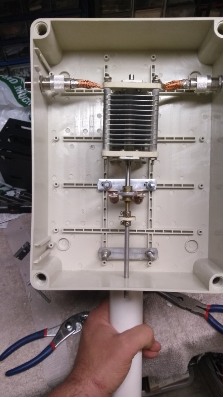
Above are the internals and the rear. I designed it so I could unscrew the top spreaders from the case to transport. There’s enough room in the box for a gear reduction motor for remote operation in the future. N type connectors on the sides, are soldered to the outside shield from some RG8 coax(center insulator and conductor was remove to make more of a braid).
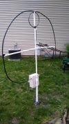
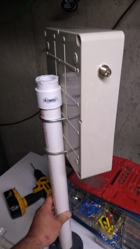
Here is the entire thing outside. Not a perfect circle, but it works just fine. Small loop just connect the outside shield to the center pin of the PL-259, and then on the other end connect the shield to the outside ground or shield of the PL-259 connector. Pretty amazing that short loop isn’t a short when its tuned up properly.
Side spreaders are just pressed into the cross pipe so I can take it apart.
Now for the comparisons…
I chose to operate FT8 at 40 watts when I did this to show what stations heard my signal using https://www.pskreporter.info/pskmap.html
I think this will be more subjective than trying to convey signal reports on SSB, though I’ve made contacts just fine with it with 50 watts.
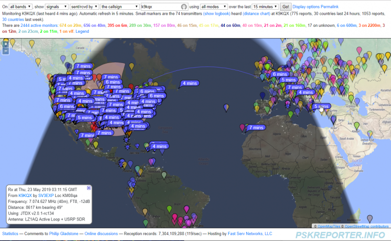
Mag Loop on 40M @ 40 watts around 10pm facing East West direction (click image to expand).
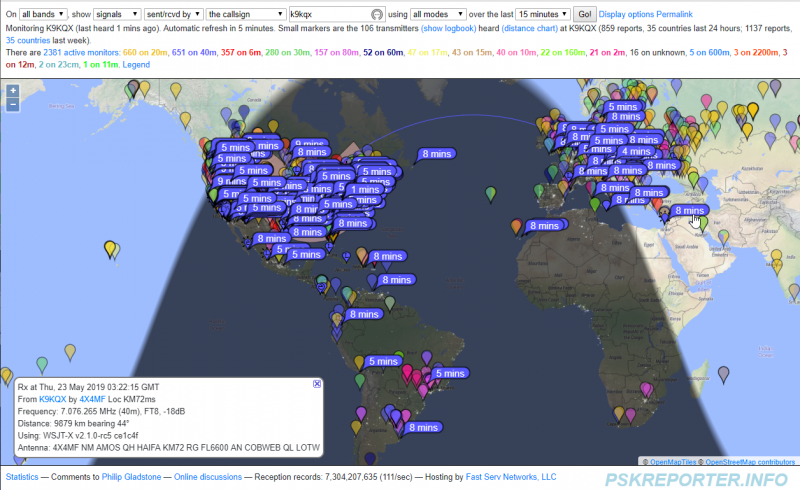
Now on my 40m Fan dipole @ 40 watts around 10:30pm, slightly inverted V at almost 30 feet (click image to expand).
Reception Comparisons
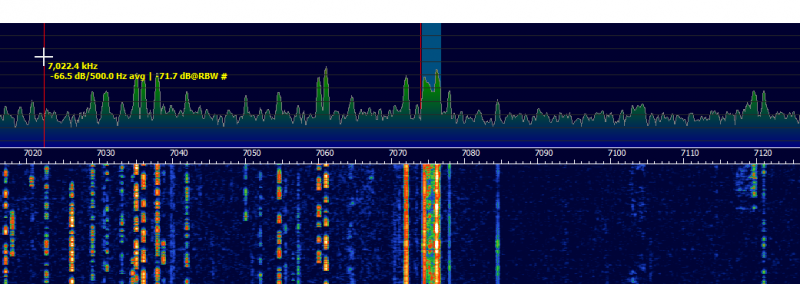
Magnetic Loop Receive – Below is a view of the panadapter, notice how there is a pronounced peak where the antenna is tuned and as you deviate from that the received signal gets weaker (click image to expand).
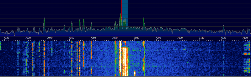
Dipole Receive – Below is a screen shot of the panadapter, you can see that the receive is has a flat response across the entire band (click image to expand).
It’s not surprising the Dipole does work better, but think about it, It took me a long time to get that up in the trees, tune it, maintain it during storms. I bet I worked on that thing over the course of a year to really finally have something I could raise and lower to maintain all through trial and error.
On the other hand, I spent a Friday night and a Sunday afternoon and had this on the air. This little Magnetic Loop does remarkable well, sits literally two feet off the ground. I can put it in my trunk, takes all of 5 minutes to put it together at a remote site and the results are pretty darn good. Another positive I noticed, reduced static crashes, about 2 S units typically. I can rotate it to focus on certain areas to work. I does have a narrow bandwidth, but that could be a good thing during a field day with multiple transmitters as you might not get interference from the others working nearby.
So there you have it, some actual comparisons. For all those living in HOA’s, no trees, no tower, etc, this really could be the difference from not operating to getting on the air.
Mike Sorensen, K9KQX