By: Bill Crockett, KD9AUP
Here is a description of my homebrew loop antenna, together with photos of construction.
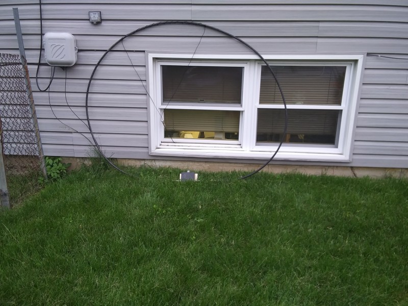
1) 16ft of Coax or other large low impedance cable or Pipe. (No connection is made to the Center conductor, only the shield.) (I used a left over piece of Heliax.) (5 ft diameter)
2) # 16 AWG Stranded wire wrapped around Coax 11 turns over a span centered at the top of 46 “
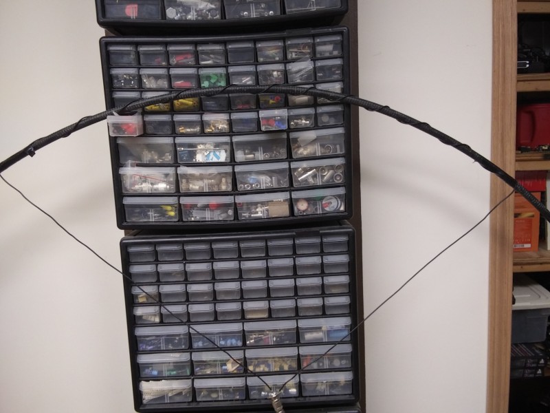
3) The connector in the middle is at the end of approximately 27 ” wires
4) The turns were expanded or compressed to gain best SWR performance on 20 and 40 meters, middle of these is 1:1 to 1 at resonance (about 1;7 to 1 on the extremes for 20 and 40 meters).
5) Hamfest special Tuning capacitor $10 good for around 2KV 20-320 PF. The capacitance on the high end (20 Meters was still excessive capacitance), I think around 5pf is more desirable up to around 165pf for the low end. I removed 7 sets of Plates to reduce capacitance, double spaced the existing plates to raise the voltage (Larger gap) then adjusted the offset from plates in the center to gain enough capacitance for 40 Meters. This was multi iterative to get best performance on both band edges. This was tested at 100 Watts no issues.
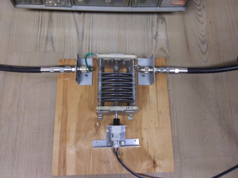
6) Motor mounting bracket out of .062 6041 aluminum I was off on my right angle bend so just used a piece of Right angle aluminum to space it up.
7) Flexible Resin based coupler for motor to capacitor, this can be easily be drilled to the diameters required for the Motor shaft and the Capacitor shaft.
8) Parts mounted on a 1/4 ‘ piece of scrap plywood w/ Sheet metal screws, feet on bottom as screws were longer than plywood so they protruded on reverse side. Use a plastic box for outside weather proofing.
9) DPDT Switch with a dropping voltage regulator to get enough voltage to the motor for torque and slow the RPMs down a bit to make tuning easier.
10) Capacitor position is quite critical to resonance, slower speeds would provide some better granularity, Capacitor is tweaked for max S units signal, or noise.
11) Initial tuning to find SWR’s was done with an MFJ 259.
I am in hopes that others will explore this antenna and this provides yet another coupling approach using commonly available junk parts.
Regards,
Bill, KD9AUP