AntSDR T510 AI Pre-Launch
Direct RF Input Up to 2 GHz Baseband Bandwidth per Channel
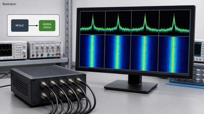
Here is an ambitious software-defined radio project for SARC members who enjoy radio, software, signal processing, and hands-on experimentation. The AntSDR T510 AI combines a high-speed RF system-on-chip with an integrated NVIDIA Jetson computing module. That pairing is intended to move signal capture, digital processing, visualization, and AI-assisted analysis onto one platform.[1]
Pre-launch note: As of August 19, 2026, the official Crowd Supply page labels this project “Coming Soon.” It does not list an official price, order date, campaign date, or shipping schedule. Product details may change, so readers should check the official project page before making plans or purchases. RTL-SDR.com reported the pre-launch announcement on August 18, 2026.[1][2]
Topic Snapshot
| Item | Details |
|---|---|
| Subject | An integrated computing platform for real-time wireless sensing |
| Product | AntSDR T510 AI |
| Project status | Pre-launch; the official page says “Coming Soon” |
| Published RF coverage | Direct RF input coverage from 1 MHz to 6 GHz |
| Published bandwidth | Up to 2 GHz of baseband bandwidth per channel |
| Core architecture | AMD Zynq UltraScale+ RFSoC ZU47DR, eight ADC channels, eight DAC channels, and an integrated NVIDIA Jetson module |
| Post idea from | Paul Meyers – KE9EJX |
| Audience | SARC members, visitors, new hams, the public, and operators |
| Key question | How would you use the ANTSDR-T510? |
The status and specifications in this snapshot come from the current MicroPhase project page.[1]
What Is the AntSDR T510 AI?
SDR means software-defined radio. In a conventional radio, many operating functions are fixed in hardware. An SDR moves functions such as tuning, filtering, modulation, demodulation, and spectrum display into digital processing.
The T510 AI takes that idea much further than a typical USB receiver. MicroPhase says the platform uses an AMD Zynq UltraScale+ RFSoC ZU47DR. RFSoC means radio-frequency system-on-chip. It combines high-speed RF data converters, programmable logic, and embedded processors in one device.
The RFSoC Handles Fast, Predictable Processing
The platform supports digital mixing, digital downconversion and upconversion, interpolation, decimation, buffering, and multichannel synchronization. A digital downconverter, often shortened to DDC, selects and reduces a portion of a sampled signal for further processing. A digital upconverter, or DUC, prepares a digital signal for conversion back toward RF.
The published architecture includes eight synchronized 14-bit analog-to-digital converter channels operating at up to 5 GSPS and eight synchronized 14-bit digital-to-analog converter channels operating at up to 9.85 GSPS. GSPS means billions of samples per second. The manufacturer describes this as an 8T8R architecture: eight transmit converter channels and eight receive converter channels.[1]
Those numbers describe converter resources. They do not, by themselves, confirm eight independent full-duplex radios, maximum usable sensitivity, transmitter power, or the amount of data that can be recorded from every channel at once.
The Jetson Handles Parallel Computing
The integrated NVIDIA Jetson module is intended for graphics-processing-unit, or GPU, workloads. That may include spectrum analysis, matrix calculations, feature extraction, and AI inference. Inference means applying a trained model to new data.
The official specifications identify an NVIDIA Jetson module, while the power-consumption note refers generally to “Jetson NX @15W” without giving an exact model number. RTL-SDR’s report alternates between Jetson Orin Nano and Jetson Orin NX. Therefore, neither model should be treated as confirmed until MicroPhase publishes the final configuration.[1][2]
Understanding the Headline Specifications
| Published item | Plain-language meaning | Important limit or question |
|---|---|---|
| 1 MHz to 6 GHz | The official page states direct RF input coverage across this range. | This is not permission to transmit everywhere in the range. The page does not separately publish complete transmitter coverage or output specifications. |
| Up to 2 GHz per channel | This is the stated maximum baseband bandwidth available in the digital front end. | It does not confirm that all eight channels can simultaneously stream or record 2 GHz each to the Jetson, a host computer, or storage. |
| 8T8R | The design includes eight ADC and eight DAC channels with synchronization. | Port routing, full-duplex behavior, isolation, calibration accuracy, and phase-coherence limits still need confirmation. |
| Clocking and timing | The page lists external, onboard oven-controlled or temperature-compensated crystal oscillator options (OCXO or TCXO), and GPS clock options, plus PPS triggering and multi-board synchronization. | The required accessories and achievable timing accuracy are not stated. |
| High-speed connections | The RFSoC side lists a 100 G QSFP28 high-speed optical interface. The platform also lists Gigabit Ethernet and USB, plus Jetson-side USB, HDMI, Ethernet, and M.2 SSD expansion. | The official page does not publish an end-to-end sustained streaming or recording rate for any simultaneous-channel configuration. |
| Software | The official page advertises Ubuntu 22.04 with NVIDIA’s GPU development platform, CUDA, plus WaveSight, GNU Radio, SoapySDR, an IQTAXI driver framework, and Python or C++ development. | Drivers, examples, documentation, and open-source resources are still developing during the pre-launch period. |
These published specifications are summarized from the official MicroPhase project page.[1]
MicroPhase says WaveSight is intended to visualize, monitor, record, and replay as many as eight synchronized RF channels. The same page advertises GNU Radio and SoapySDR compatibility and a SignalLab AI demonstration for classifying Wi-Fi, Bluetooth, and modulation types.[1]
MicroPhase says additional hardware references, firmware sources, high-speed transfer examples, bare-metal demonstrations, and Jetson workflows are planned. The public GitHub repository already contains image-building resources, but its README says detailed documentation will be added later. That is a useful reminder to treat the software environment as evolving.[1][3]
How It Works
The following diagram is a simplified educational view. A real station may also need band-specific filters, attenuators, amplifiers, switches, input protection, calibration, test equipment, and suitable antennas.
---
config:
  markdownAutoWrap: true
  flowchart:
    wrappingWidth: 220
    useMaxWidth: true
    nodeSpacing: 40
    rankSpacing: 50
---
flowchart TD
    A["`Choose a receive-only
or licensed experiment`"]

    B{"`Choose a
project path`"}

    C["`Connect an antenna or lab source
through suitable input protection`"]

    D["`ADC and RFSoC:
sample, synchronize, filter,
and channelize`"]

    E["`Jetson or host:
display, classify, or record`"]

    F["`Generate a test waveform
under operator control`"]

    G["`RFSoC and DAC:
process and convert`"]

    H["`Use a dummy load or shielded
test setup first`"]

    I["`Measure emissions and add
proper filtering before
connecting an antenna`"]

    A --> B

    B -->|"Receive"| C
    C --> D
    D --> E

    B -->|"Transmit"| F
    F --> G
    G --> H
    H --> I
What Could SARC Members Explore?
The ideas below are possible learning projects based on the published architecture. They are not promises about final product performance.
Build a Receive-Only Spectrum Demonstration
Start with one receive channel and a narrow, known portion of an amateur band. Use GNU Radio or WaveSight to show a waterfall, select a signal, change the sample rate, and demonstrate decimation. This gives newer hams a clear view of how bandwidth and digital filtering work.
Compare Antennas with Synchronized Channels
Two or more synchronized inputs could support experiments that compare antennas, polarization, phase, or arrival time using a known club signal or amateur beacon. Accurate direction-finding or phased-array work would require careful channel calibration, matched RF paths, and a well-designed antenna array.
Study FPGA, CPU, and GPU Workloads
If the released firmware and development files expose the required processing paths, a club team could compare how a fast Fourier transform, filter, or channelizer is implemented with embedded processing, FPGA logic, and the Jetson GPU. This would show why some work belongs in deterministic FPGA logic while other work fits a CPU or GPU. A fast Fourier transform, or FFT, converts sampled data into a frequency display.
Evaluate Signal Classification
Members interested in AI could train or test a classifier using SARC’s own labeled recordings, generated test signals, or known amateur modes. Keep a human in the loop. Compare the model’s result with a normal spectrum display and documented measurements. Classification is not the same as guaranteed identification, decoding, or understanding.
Experiment with Timing and Multiple Channels
The published clock and pulse-per-second features suggest projects involving synchronized measurements. PPS is a precise timing pulse often supplied by a GPS-disciplined source. A project could compare timestamps or phase across channels while documenting the limits of the setup.
A Practical Way to Start
- Write one clear question. For example: “Can two synchronized receivers measure the phase difference from a known 2-meter beacon?”
- Choose the smallest useful bandwidth. A voice, digital-mode, or beacon experiment does not need a 2 GHz data stream.
- Begin receive-only. Use a known signal and learn the software before adding a transmit path.
- Plan the RF front end. Select an antenna, band-pass filter, attenuator, input protection, and low-noise amplifier only when the experiment requires them.
- Plan the data path. Estimate channel count, sample format, rate, storage, and recording time before collecting data.
- Record the configuration. Note firmware, software, clock source, gain, frequency, sample rate, filter settings, cables, and antennas so another member can repeat the test.
What to Verify Before Ordering
Because the project is still in pre-launch, a careful buyer should confirm the following items on the official page:
- Final campaign price, included hardware, ordering terms, and shipping estimate
- Exact NVIDIA Jetson model, memory, storage, and cooling configuration
- Receiver sensitivity, noise figure, dynamic range, and input protection
- Transmit frequency coverage, output power, filtering, spectral purity, and port routing
- Maximum simultaneous channel count and sustained bandwidth for display, streaming, and recording
- Clock accuracy, channel-to-channel phase performance, and calibration procedure
- Current GNU Radio, SoapySDR, WaveSight, IQTAXI, Python, and C++ support
- Which schematics, firmware, examples, and APIs are published under open-source licenses
- Power-supply requirements, accessories, warranty, support, and applicable regulatory information
Transmit and Safety Reminder
A radio that covers a wide frequency range does not authorize transmission throughout that range. In the United States, every over-the-air amateur transmission must remain within the frequencies and privileges available to the control operator. The emission type must be authorized, the occupied bandwidth must be no wider than necessary, spurious emissions must be controlled, and the minimum power needed should be used.[4]
Start transmit development into a suitable dummy load that matches the confirmed port impedance, or use a properly shielded test setup. Verify the signal with test equipment. Then add the correct filtering and confirm connector, impedance, drive-level, power, and RF-exposure requirements before connecting an antenna or amplifier.
New and unlicensed participants can help with receive-only demonstrations, software, documentation, and data analysis. Any on-air transmission should occur under the control of an amateur operator whose license privileges authorize that frequency and emission. As a practical safeguard, AI-assisted station decisions should remain under the supervision of the control operator, who must be able to stop transmission and verify that the station is operating correctly.[4]
Suggested SARC Goals
| Member type | Suggested goal | Good first step |
|---|---|---|
| New ham or visitor | Understand a waterfall, sample rate, filter width, and decimation. | Join a supervised, receive-only demonstration using one channel. |
| Active operator | Compare antennas or filters on a familiar amateur band. | Define one known signal and one repeatable measurement. |
| Software experimenter | Build a GNU Radio, SoapySDR, Python, or C++ receive workflow. | Start with a narrow bandwidth and save the configuration. |
| RF builder | Design a protected, filtered front end for one amateur band. | Document expected signal levels before connecting the SDR. |
| AI student | Evaluate a classifier with known, labeled club signals. | Create a small test set and measure false identifications. |
| Club volunteer | Prepare a safe public demonstration. | Build a short receive-only lesson with a diagram and checklist. |
Give It a Try
The AntSDR T510 AI is not a simple plug-in receiver. It appears to be a development platform for people who want to study wideband signals, synchronized channels, programmable logic, GPU computing, and AI-assisted analysis. That also makes it a useful discussion topic for a club with members at many experience levels.
Start with one question and one receive channel. Keep the bandwidth small. Measure what the system actually does. Then add channels, timing, or GPU processing only when the project needs them.
How would you use the ANTSDR-T510? Bring a project idea to SARC. It could become a future club demonstration, article, workshop, or team experiment.
How would you use the ANTSDR-T510?
References
- AntSDR T510 AI. MicroPhase Technology, hosted by Crowd Supply. Accessed August 19, 2026. https://www.crowdsupply.com/microphase-technology/antsdr-t510-ai ↩a ↩b ↩c ↩d ↩e ↩f ↩g ↩h
- AntSDR T510 Pre-launch: A 1 MHz to 6 GHz SDR with 2 GHz Bandwidth and a Built-In NVIDIA Jetson. RTL-SDR.com. Written by admin. Published August 18, 2026. Accessed August 19, 2026. https://www.rtl-sdr.com/antsdr-t510-pre-launch-a-1-mhz-to-6-ghz-sdr-with-2-ghz-bandwidth-and-a-built-in-nvidia-jetson/ ↩a ↩b
- T510-AI Image Builder. MicroPhase Technology, GitHub. Accessed August 19, 2026. https://github.com/MicroPhase/T510-AI ↩
- 47 CFR Part 97 — Amateur Radio Service. Federal Communications Commission, Electronic Code of Federal Regulations. Accessed August 19, 2026. See especially §§ 97.13(c), 97.109, 97.301, 97.305, 97.307, and 97.313. https://www.ecfr.gov/current/title-47/chapter-I/subchapter-D/part-97 ↩a ↩b