Understanding Electromagnetic Waves
Here is a useful physics idea for Schaumburg Amateur Radio Club (SARC) members: every on-air contact begins with an electromagnetic wave. Voice, continuous wave (CW) Morse code, and digital signals all depend on radio-frequency (RF) energy traveling from a transmitting antenna to a receiving antenna. Understanding that path makes frequency, wavelength, polarization, antennas, and propagation easier to connect.[1][5]
Topic Snapshot
| Item | Details |
|---|---|
| Subject | Learn Physics: Understanding Electromagnetic Waves |
| Post idea from | Paul Meyers – KE9EJX |
| Audience | Members, visitors, new hams, the public, and operators |
| Why it matters | Electromagnetic-wave physics connects transmitters, antennas, propagation, receivers, and operating practice. |
| Starting resource | Physics with Elliot |
| Advanced resource | Richard Behiel on YouTube |
| Call to action | Learn Physics |
What Is an Electromagnetic Wave?
An electromagnetic wave is a traveling pattern of changing electric and magnetic fields. These coupled fields can carry energy through air, other materials, and even the vacuum of space. Unlike a sound wave, an electromagnetic wave does not require air or another material medium.[2][3]
James Clerk Maxwell brought the laws of electricity and magnetism together in four relationships now called Maxwell’s equations. The equations predicted electromagnetic waves traveling at the speed of light in free space. Heinrich Hertz later generated and detected radio waves in laboratory experiments, confirming their wave behavior.[2]
Radio waves are one part of the electromagnetic spectrum. Infrared, visible light, ultraviolet, X-rays, and gamma rays are also electromagnetic waves. They share the same basic physics but have different frequencies, wavelengths, and photon energies.[1]
Electric Field, Magnetic Field, and Direction
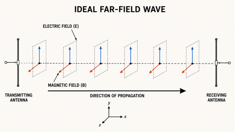
For an ideal plane wave, the electric field and magnetic field are at right angles to each other. Both are also at right angles to the direction in which the wave travels. That makes an electromagnetic wave a transverse wave. The fields rise and fall together as the wave moves forward.[3]
| Part | Direction | Why radio operators care |
|---|---|---|
| Electric field | Across one transverse direction | Its orientation defines the wave’s polarization. |
| Magnetic field | Perpendicular to the electric field | It is the second coupled field in the wave. |
| Wave travel | Perpendicular to both fields | It shows the direction in which energy is moving. |
This clean picture describes an ideal wave and is a useful far-field model. Close to an antenna, the fields are more complicated. Also, a sine-wave drawing shows how field strength and direction vary. It does not mean the radio signal follows a snake-shaped path through the air.
How an Antenna Starts the Wave
Electric charges radiate electromagnetic energy when they accelerate. In a transmitting antenna, radio-frequency alternating current repeatedly accelerates charges in the conductor. The antenna then launches energy into the surrounding space. At the other end of the path, an incoming field produces a small alternating electrical signal in the receiving antenna. The receiver selects the desired signal and recovers its information.[4][5]
Here is the simplified signal path:
---
config:
  markdownAutoWrap: true
  flowchart:
    wrappingWidth: 220
    useMaxWidth: true
    nodeSpacing: 40
    rankSpacing: 50
---
flowchart TD
    A["`The transmitter creates
a radio-frequency signal`"]

    B["`Alternating current accelerates
charges in the antenna`"]

    C["`Changing electric and magnetic
fields travel outward`"]

    D["`The electromagnetic wave
travels through space`"]

    E["`The field produces a small signal
in the receiving antenna`"]

    F["`The receiver selects and
demodulates the signal`"]

    G["`The operator hears audio
or receives data`"]

    A --> B
    B --> C
    C --> D
    D --> E
    E --> F
    F --> G
This flow is intentionally simple. A real station also includes feed lines, matching, losses, noise, modulation, and the effects of the path between stations.
Frequency, Wavelength, Speed, and Polarization
These terms describe different properties of the same wave. Learning them together is more useful than memorizing them separately.
| Term | Plain-language meaning | Amateur-radio connection |
|---|---|---|
| Frequency | The number of cycles that pass a point each second, measured in hertz (Hz) | A radio is tuned to frequency. One megahertz (MHz) is one million cycles per second. |
| Wavelength | The distance over which one complete wave pattern repeats | Many amateur bands are named for an approximate wavelength, such as 40 meters or 2 meters. |
| Amplitude | The size or strength of an oscillating field | Amplitude is one characteristic that can be varied to carry information. |
| Phase | A wave’s position within its cycle compared with a reference | Phase relationships affect interference, antenna arrays, and many digital modes. |
| Polarization | The orientation of the electric field | Common examples include horizontal, vertical, and circular polarization. |
NASA uses these same ideas to describe electromagnetic energy. The Federal Communications Commission (FCC) also describes modulation as varying a carrier waveform’s amplitude, frequency, or phase to transmit information.[1][8]
The Wavelength Formula
In a vacuum, electromagnetic waves travel at exactly 299,792,458 meters per second. This is the speed of light, represented by c.[6]
Wavelength equals wave speed divided by frequency:
λ = c ÷ f
Here, λ is wavelength and f is frequency. For quick amateur-radio estimates in free space, use:
Wavelength in meters ≈ 300 ÷ frequency in MHz
Therefore, when frequency goes up, wavelength gets shorter. When frequency goes down, wavelength gets longer. The free-space formula is a starting point for antenna calculations. Practical antenna dimensions must also account for the actual design and installation.[3][17]
Frequency and Wavelength at a Glance
| Approximate band name | Representative frequency | Approximate free-space wavelength |
|---|---|---|
| 80 meters | 3.75 MHz | 80.0 meters |
| 40 meters | 7.10 MHz | 42.3 meters |
| 20 meters | 14.20 MHz | 21.1 meters |
| 15 meters | 21.20 MHz | 14.2 meters |
| 10 meters | 28.40 MHz | 10.6 meters |
| 2 meters | 146 MHz | 2.05 meters |
| 70 centimeters | 440 MHz | 0.682 meter |
---
config:
  theme: base
  themeVariables:
    xyChart:
      titleColor: "#000000"
      dataLabelColor: "#000000"
      xAxisLabelColor: "#000000"
      xAxisTitleColor: "#000000"
      xAxisTickColor: "#000000"
      xAxisLineColor: "#000000"
      yAxisLabelColor: "#000000"
      yAxisTitleColor: "#000000"
      yAxisTickColor: "#000000"
      yAxisLineColor: "#000000"
  xyChart:
    width: 900
    height: 540
    useMaxWidth: true
    chartOrientation: vertical
    titleFontSize: 18
    titlePadding: 18
    showDataLabel: true
    showDataLabelOutsideBar: true
    plotReservedSpacePercent: 62
    xAxis:
      labelFontSize: 13
      labelPadding: 8
      labelRotation: 0
      titleFontSize: 16
      titlePadding: 8
    yAxis:
      labelFontSize: 13
      labelPadding: 8
      titleFontSize: 15
      titlePadding: 8
---
xychart-beta
    title "Higher Frequency Means Shorter Wavelength in Free Space"
    x-axis "Frequency" ["3.75 MHz", "7.10 MHz", "14.20 MHz", "21.20 MHz", "28.40 MHz"]
    y-axis "Approximate Wavelength in Meters" 0 --> 90
    bar [80.0, 42.3, 21.1, 14.2, 10.6]
The table and graph use the free-space shortcut. Band names are approximate, and wavelength changes across a band. These numbers are not finished antenna lengths. A physical antenna is designed for a chosen fraction or multiple of wavelength and must be adjusted for its actual construction and installation.[6][10][17]
How Electromagnetic Waves Behave
A radio wave does not always travel by one clear, direct path. Depending on frequency and surroundings, electromagnetic waves may be reflected, refracted, diffracted, scattered, transmitted, or absorbed. Buildings, terrain, the ground, the atmosphere, and the ionosphere can all affect the signal that reaches a receiver.[7]
For example, high frequency (HF) signals can sometimes be bent through the ionosphere and returned toward Earth. This supports contacts beyond the horizon. Very high frequency (VHF) and ultra high frequency (UHF) operation is often closer to line of sight, although special propagation modes can extend the range. Conditions change, so operators learn to observe the band rather than expect the same result every day.[9][10][19]
Why This Matters in Amateur Radio
A working understanding of electromagnetic waves helps an operator connect several practical ideas:
- Antenna dimensions: Wavelength provides a starting point for quarter-wave, half-wave, and other antenna designs.[17]
- Polarization: The orientation of the electric field helps explain why antenna alignment can affect received signal strength.
- Propagation: Frequency and wavelength influence how signals interact with terrain, buildings, the atmosphere, and the ionosphere.
- Modulation: Information can be carried by controlled changes to a radio wave’s amplitude, frequency, or phase.
- License study: The current Technician syllabus includes electromagnetic-wave properties, frequency and wavelength, polarization, and propagation. Candidates should check the official question pool for updates.[10][20]
Physics will not choose every station setting for you. However, it gives you a reliable framework for asking better questions and understanding what you observe on the air.
How to Participate: Learn and Apply the Physics
Start with Physics with Elliot
Physics with Elliot offers a visual route into physics. A useful lesson for this topic is There’s so much more to electric fields than you were taught. It moves from the electric field of a stationary charge toward moving charges, accelerated charges, and electromagnetic radiation.[11]
For a shorter visual, try Discovering the simplest electromagnetic wave! The site also has an Electric Field Lines interactive animation. The animation focuses on static electric fields rather than radio propagation, but it can help build intuition about what a field represents.[12][13]
Physics with Elliot is a general physics resource. Use amateur-radio references for antenna construction, station safety, operating rules, and band privileges. Video catalogs and course offerings may change, so check the official site for current material.
Try a Simple Station Exercise
What to bring: A calculator, one frequency of interest, basic information about the antenna, and a current band chart. A radio is optional because the calculation can be done from any example frequency.
- Choose a frequency you use or monitor.
- Divide 300 by the frequency in MHz to estimate the free-space wavelength in meters.
- Compare your answer with the band’s familiar name.
- For a simple linearly polarized antenna, estimate polarization from the orientation of its radiating element.
- Trace the path from transmitter to feed line, antenna, space, receiving antenna, and receiver.
- List anything along the path that might reflect, absorb, bend, or scatter the signal.
For example, 300 divided by 146 MHz is about 2.05 meters. That helps explain the name “2-meter band.” A free-space half wavelength would be about 1.03 meters, but a practical half-wave antenna may have a different finished length.[17]
Take an Optional Deeper Dive with Richard Behiel
Readers who enjoy mathematical physics can visit the Richard Behiel YouTube channel. His long-form video Electromagnetism as a Gauge Theory develops electromagnetism through symmetry, fields, and Maxwell’s equations.[14][15]
This is an advanced lesson, not a beginner amateur-radio tutorial. Start with frequency, wavelength, fields, and polarization. Then use Richard Behiel’s presentation when you are ready for the deeper mathematics.
Check Current Operating Information
Physics relationships are stable, but frequency allocations, license privileges, and operating rules can change. Before transmitting, check current Federal Communications Commission information and an up-to-date amateur band chart.[16][18]
Suggested SARC Goals
| Member type | Suggested goal |
|---|---|
| Visitor or member of the public | Explain in plain language that radio waves are one part of the electromagnetic spectrum. |
| New ham | Choose one operating frequency and calculate its approximate free-space wavelength. |
| Active operator | Trace the path from transmitter to antenna to receiver, then identify the polarization used by the station. |
| Antenna builder | Compare free-space wavelength with the dimensions of one antenna design and note why practical dimensions differ. |
| Mentor or volunteer | Use the signal-path diagram to explain electromagnetic waves to someone new to amateur radio. |
Give It a Try
You do not need to solve all of Maxwell’s equations before the physics becomes useful. Start with one frequency, calculate its wavelength, look at the antenna, and trace the signal path. Then share what you found with another SARC member or visitor.
Learn Physics with Physics with Elliot
References
- Anatomy of an Electromagnetic Wave. NASA Science, Science Mission Directorate, National Aeronautics and Space Administration. Updated August 3, 2023. Accessed August 12, 2026. https://science.nasa.gov/ems/02_anatomy/
- Samuel J. Ling, William Moebs, and Jeff Sanny. 16.1 Maxwell’s Equations and Electromagnetic Waves. University Physics Volume 2, OpenStax, Rice University. Published October 6, 2016. Accessed August 12, 2026. https://openstax.org/books/university-physics-volume-2/pages/16-1-maxwells-equations-and-electromagnetic-waves
- Samuel J. Ling, William Moebs, and Jeff Sanny. 16.2 Plane Electromagnetic Waves. University Physics Volume 2, OpenStax, Rice University. Published October 6, 2016. Accessed August 12, 2026. https://openstax.org/books/university-physics-volume-2/pages/16-2-plane-electromagnetic-waves
- Paul Peter Urone and Roger Hinrichs. 24.2 Production of Electromagnetic Waves. College Physics 2e, OpenStax, Rice University. Published July 13, 2022. Accessed August 12, 2026. https://openstax.org/books/college-physics-2e/pages/24-2-production-of-electromagnetic-waves
- Jermaine Walker. Radio vs Optical Spectrum. National Aeronautics and Space Administration. Published September 27, 2023; updated February 14, 2024. Accessed August 12, 2026. https://www.nasa.gov/directorates/somd/space-communications-navigation-program/radio-vs-optical-spectrum/
- CODATA Value: Speed of Light in Vacuum. National Institute of Standards and Technology. Accessed August 12, 2026. https://physics.nist.gov/cuu/Constants/Value/c.html
- Wave Behaviors. NASA Science, Science Mission Directorate, National Aeronautics and Space Administration. Updated August 3, 2023. Accessed August 12, 2026. https://science.nasa.gov/ems/03_behaviors/
- Report and Order, FCC 23-93. Federal Communications Commission. Adopted November 13, 2023. Accessed August 12, 2026. https://docs.fcc.gov/public/attachments/FCC-23-93A1.pdf
- Propagation of RF Signals. American Radio Relay League. Accessed August 12, 2026. https://www.arrl.org/propagation-of-rf-signals
- Chapter 10: Technician Class Syllabus. American Radio Relay League. Effective July 1, 2026, through June 30, 2030. Accessed August 12, 2026. https://www.arrl.org/files/file/Education/TechnicianClass/HRLM%206th-Ch%2010%20QPOOL.pdf
- Elliot Schneider. There’s so much more to electric fields than you were taught. Physics with Elliot. Accessed August 12, 2026. https://www.physicswithelliot.com/videos/v/cy9tefze46pktezdxe2tz2rfe6sbd7
- Elliot Schneider. Electric Field Lines. Physics with Elliot. Accessed August 12, 2026. https://www.physicswithelliot.com/electric-field-lines
- Elliot Schneider. Discovering the Simplest Electromagnetic Wave! Physics with Elliot, YouTube. Accessed August 12, 2026. https://www.youtube.com/shorts/PH_PJiPyObc
- Richard Behiel. Richard Behiel, YouTube channel. Accessed August 12, 2026. https://www.youtube.com/@RichBehiel
- Richard Behiel. Electromagnetism as a Gauge Theory. YouTube. Accessed August 12, 2026. https://www.youtube.com/watch?v=Sj_GSBaUE1o
- Radio Spectrum Allocation. Federal Communications Commission. Accessed August 12, 2026. https://www.fcc.gov/engineering-technology/policy-and-rules-division/general/radio-spectrum-allocation
- Single Band Dipoles. American Radio Relay League. Accessed August 12, 2026. https://www.arrl.org/single-band-dipoles
- 47 CFR Part 97 — Amateur Radio Service. Electronic Code of Federal Regulations, National Archives and Records Administration. Accessed August 12, 2026. https://www.ecfr.gov/current/title-47/chapter-I/subchapter-D/part-97
- Solar Flares (Radio Blackouts). Space Weather Prediction Center, National Oceanic and Atmospheric Administration and National Weather Service. Accessed August 12, 2026. https://www.spaceweather.gov/phenomena/solar-flares-radio-blackouts
- Question Pools. American Radio Relay League. Accessed August 12, 2026. https://www.arrl.org/question-pools