Maidenhead EN Ham Radio Performance
Executive summary
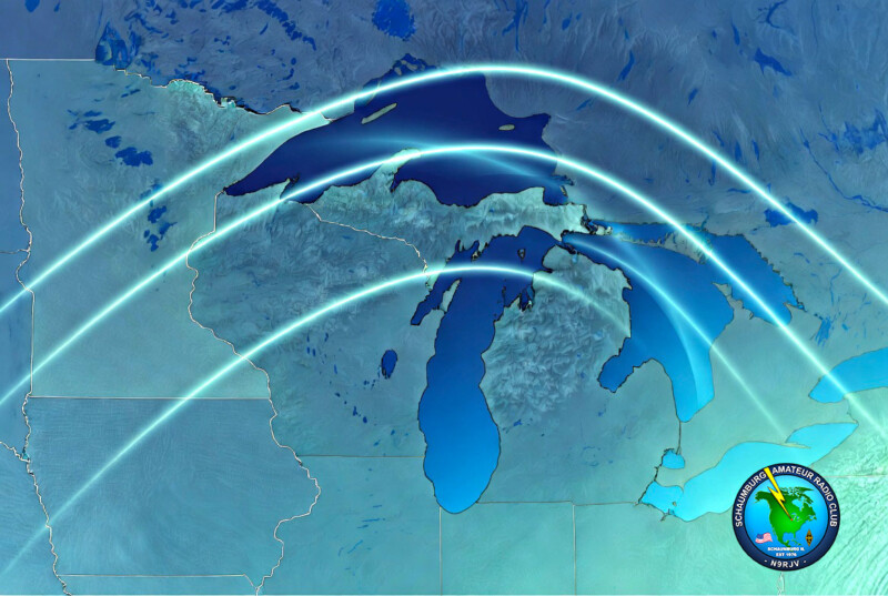
We define “EN” as the eastern-northern portion of the Midwest, this report treats it as an operationally defined Great Lakes / eastern-northern Midwest subregion.
For early June 2026, the official space-weather picture is usable but variable rather than quiet-stable. NOAA SWPC’s June 4 forecast expected low-to-moderate solar activity, with chances for R1–R2 radio blackouts from active regions, and active to G1 geomagnetic conditions with a minor chance of stronger disturbance. SWPC defines R1 as weak/minor HF degradation on the sunlit side. The smoothed June 2026 solar-cycle forecast also remained elevated, with a predicted sunspot number near 101.3 and F10.7 near 126.3, which is still favorable for daytime F-region support on 20–10 meters compared with solar-minimum years.
For the Midwest EN region, that translates into a practical HF pattern of stronger daytime potential on 20/17/15 meters, intermittent but still meaningful opportunities on 12/10 meters, and less stable 40/80-meter daytime performance whenever D-layer absorption is elevated. After sunset, the D layer weakens, so 40 and 80 meters typically become the more reliable regional/interregional bands, while 20 meters often stays usable later into the evening in summer. This seasonal/diurnal pattern is an inference from NOAA’s D-region absorption product, ionospheric reflection physics, and current Cycle 25 flux levels.
On 2 m / 70 cm / 23 cm, ordinary range remains mostly line-of-sight plus scatter, but the Great Lakes and adjacent flat terrain can produce useful tropospheric enhancement when high pressure, subsidence inversions, nocturnal cooling, and lake/land temperature contrasts align. A long-running engineering summary of William Hepburn’s tropo maps notes that ducting is more common in the Midwest, Great Lakes, and Northeast in fall, though early-summer overnight lake-path enhancements still occur under stable air. NOAA and NWS sources also show why: the Great Lakes cool nearby summer air, generate lake-breeze circulations, and help support shallow stable layers along lake paths.
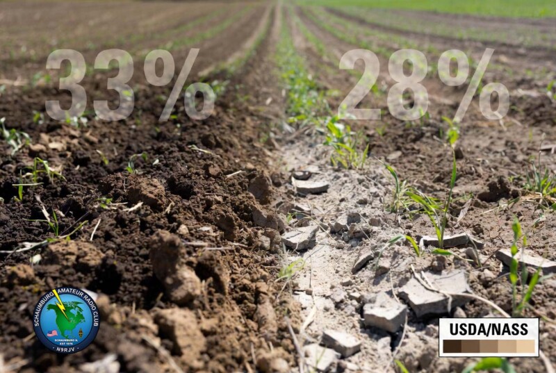
The soil side of the problem is at least as important as the sky side for verticals and ground-mounted antennas. USDA/NASS data for the week ending May 31, 2026 showed that parts of the eastern-northern Midwest were drying quickly even without widespread formal drought: Illinois topsoil in the “very short + short” categories was 33%, Michigan 28%, Minnesota 35%, and Wisconsin 34%, while Ohio was still only 1% and Indiana 15%. CPC’s June outlook simultaneously favored subnormal precipitation across the Great Lakes and adjacent areas, and CPC’s hazards outlook flagged rapid-onset drought possible for parts of the Upper/Middle Mississippi Valley, Ohio Valley, and Great Lakes region.
That matters because soil moisture is a major control on ground conductivity and permittivity. ITU-R states that moisture content is the major factor in ground electrical properties, and gives a striking order-of-magnitude example: loam that is normally around 10⁻² S/m can dry to about 10⁻⁴ S/m, roughly the conductivity of granite. USDA/NRCS similarly notes that wetter soils conduct better, and soil-science literature models bulk soil conductivity as a function of both volumetric water content and the conductivity of the soil solution. In other words, seasonal drying can create a several-fold to ~100× conductivity penalty depending on texture, salts, and moisture history.
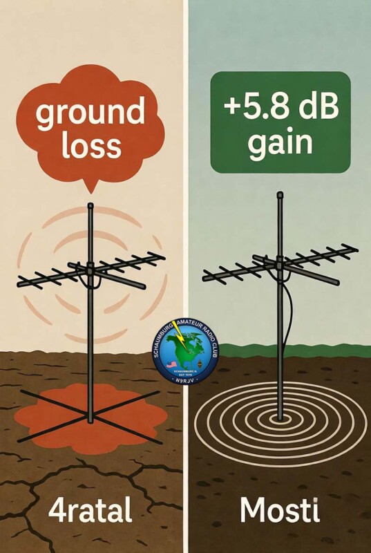
For operators, the most actionable finding is this: do not expect a ground rod to replace radials. ARRL explicitly states that a ground rod is useful for safety/lightning functions, but its RF resistance is high; a quarter-wave vertical needs a low-RF-resistance return path, which is what radial wires supply. In N6LF’s classic QEX measurements, 64 radials on the ground improved signal by about +5.8 dB relative to a sparse 4-radial baseline, while 4 elevated radials at about 48 inches produced about +5.9 dB, essentially matching the 64-radial on-ground case on 40 meters. Conversely, he described a 4-radial on-ground system as an emergency measure.
The practical implication for the Midwest EN region during dry spells is straightforward: if your vertical suddenly “still tunes, but gets out worse,” suspect ground loss before blaming the rig. The most effective mitigations are to add radials, especially in the first fraction of a wavelength from the base; consider resonant elevated radials if you cannot lay many ground radials; use an antenna analyzer to track the feedpoint resistance/reactance shift rather than relying only on shack SWR; and, for safety/lightning, test the grounding electrode separately with a ground-resistance tester using methods aligned with IEEE 81, recognizing that this does not measure RF radial performance.
Scope and assumptions
For this report, “Midwest EN” is treated as the eastern-northern Midwest / Great Lakes arc, with emphasis on Wisconsin, Michigan, Illinois, Indiana, Ohio, and adjacent upper-Midwest contexts such as Minnesota when regional soil-moisture or propagation patterns matter. That is a practical definition, not a formal one. The overlap with the Maidenhead EN field is worth noting because PSKReporter and VHF/UHF operators often think in grid fields, but I have not assumed your “EN” means only the grid field.
A second assumption is methodological: for “current” propagation, I prioritize official SWPC/CPC/USDA products and current measurement networks over anecdotal on-air reports. PSKReporter and WSPRnet are therefore treated as observational networks, not as deterministic forecasts; NOAA SWPC and CPC products are treated as the official baseline for space weather and drought/soil-moisture outlooks.
Propagation across the Midwest EN region
HF behavior
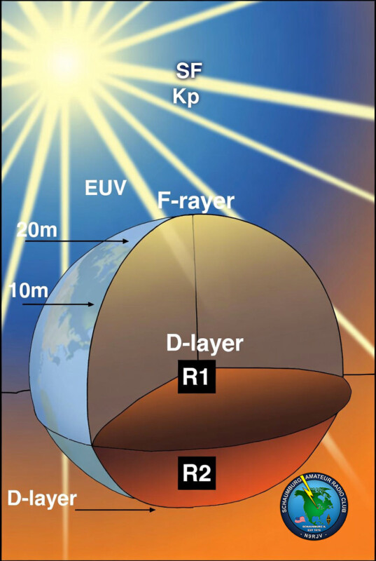
The official June 4 SWPC forecast called for low-to-moderate solar activity, with chances for M-class flares and R1–R2 radio blackouts, while geomagnetic conditions were expected to be elevated to G1 with a minor chance of stronger disturbance. SWPC’s definitions matter here: R1 already implies weak/minor HF degradation on the sunlit side, and Kp-driven geomagnetic disturbance affects users of radio signals reflected by or passing through the ionosphere.
For Midwest EN operators, the practical pattern is therefore a two-track HF day. On the one hand, the still-elevated Cycle 25 background supports daytime 20/17/15 m very well and keeps 12/10 m genuinely worth checking, especially around local late morning through mid-afternoon. On the other hand, any R1–R2 intervals and elevated D-region absorption will most obviously punish 40/30/20 m sunlit paths at the lower end of HF, with the strongest daytime degradation usually on the lower HF bands. This is an inference from SWPC’s D-RAP absorption model and ionosonde reflection physics combined with the current smoothed sunspot/F10.7 forecast.
The seasonal pattern in early summer is classic midlatitude behavior. Longer daylight and stronger solar illumination raise daytime ionization, which helps the upper HF bands, but they also raise D-layer absorption, which is why 40 and 80 meters can feel “dead” by day and then recover sharply after sunset. In winter, the balance shifts: daytime absorption is lower, so 80 and even 160 meters improve materially, while summer still favors the upper bands more often. The spring and fall transition seasons often bring the best all-around balance between low daytime absorption and still-healthy F-region support. The seasonal summary here is a first-principles inference from the official D-layer and ionospheric references rather than a single Midwest-specific climatology product.
A useful mental model for the region is:
HF propagation drivers in the Midwest EN region (early June 2026)
→ F-region ionization
→ R1–R2 blackouts
→ 40/30/20 m daytime fading
→ Erratic path quality
→ D-layer decay → 40/80 m recovery
Strong 20–10 m daytime openings
Variable lower-HF sunlit paths
This diagram summarizes SWPC’s official HF-degradation and ionospheric mechanisms and the diurnal transition most relevant to Midwest operators.
VHF and UHF behavior
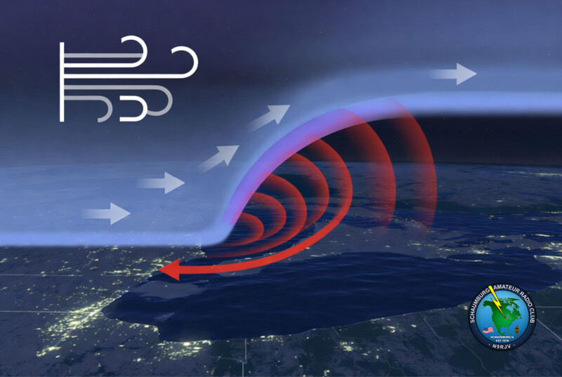
For 2 m, 70 cm, and 23 cm, most ordinary Midwest EN operating remains local or regional LOS/scatter, but VHF/UHF enhancement becomes dramatically better when the lower troposphere forms refractive ducts or strong super-refraction layers. NTIA’s classic ducting review explains that atmospheric stratification can strongly alter service and interference fields, while the NAB summary of Hepburn’s maps explains the practical recipe: warm, dry air overriding cooler, moister air produces the vertical refractive gradients that favor VHF/UHF bending and ducting.
For the Great Lakes slice of the Midwest EN region, lake physics help. NOAA-reviewed Great Lakes climatology notes that the lakes moderate temperatures, cool nearby summers, and warm nearby winters, and NWS defines the lake breeze as a thermally produced circulation from the lake toward shore caused by differential heating. Alongshore and cross-lake paths therefore get exactly the kind of shallow stable layers and inversion boundaries that can support overnight or morning tropo enhancement, especially when a synoptic high settles in and winds stay light.
The important seasonal nuance is that the Midwest/Great Lakes are not at peak tropo season in early June. The Hepburn/NAB climatological note says the fall is more favorable for the Midwest, Great Lakes, and Northeast. So the rigorous way to say it is: local VHF/UHF ducting risk is present in early summer but not climatologically maximal; expect the best odds on overnight to early-morning lake paths and during stable high-pressure episodes, with a stronger regional tendency later in summer into fall.
Observation sources and recent maps
The most useful official HF nowcasting product is NOAA SWPC’s D-Region Absorption Predictions, which SWPC explicitly describes as guidance for understanding HF radio degradation and blackouts. SWPC’s broader product suite also includes Planetary K-index, GloTEC, and WAM-IPE links, which are the right official context layers when you want to decide whether a bad day is caused mainly by absorption, geomagnetic disturbance, or background electron-content structure.
For actual on-air observation, PSKReporter is the fastest practical lens into what the bands are really doing. PSKReporter says its purpose is to automatically gather digimode reception records and make them available in near real time. Its public MQTT mirror also makes clear that spots can be filtered by band, mode, callsign, grid square, or field, which is why it is especially useful for a Midwest EN operator trying to separate “the band is shut” from “my station is underperforming.”
WSPRnet fills a slightly different niche. Its own site presents a Map, Activity, and Database, and publishes frequency coverage from LF through microwave, including 144 MHz, 432 MHz, and 1296 MHz. Because WSPR transmissions are structured for weak-signal propagation reporting, WSPRnet is excellent for night-to-night A/B comparisons of antenna changes, radial additions, drying-soil effects, and sunset/sunrise behavior, especially if you hold power, band, and schedule constant.
For planned-path work rather than nowcasting, VOACAP Online remains a standard planning tool, while real-time ionosonde-based tools such as KC2G’s MUF map are useful secondary references. These are not substitutes for local observation, but they are good for answering, “Should 15 m exist at all right now?” before you diagnose your station.
For VHF/UHF, the two practical maps are different in purpose. Hepburn’s tropo forecast is a forecast of refractive potential; VHF DX View is a real-time observation layer based on APRS-IS paths and highlights unusually long 144 MHz behaviors. Used together, they let you distinguish “forecast improvement” from actual enhancement already in progress.
Soil moisture, drought, and what that means for conductivity
The current broad drought picture is mixed, not uniformly severe. The U.S. Drought Monitor notes that drought categories run from D0 through D4, while CPC’s June 2026 Midwest discussion said that, outside Kentucky and adjacent southeastern Missouri, there was very little drought elsewhere in the Midwest, limited mainly to north-central Minnesota and some western fringes. At the same time, CPC’s June outlook favored subnormal precipitation across the Great Lakes and adjacent areas, and the weekly hazards outlook flagged rapid-onset drought possible for parts of the Upper/Middle Mississippi Valley, Ohio Valley, and Great Lakes region.
That broad-scale picture can hide rapid surface drying, which is what RF ground systems care about first. USDA/NASS weekly topsoil data for the week ending May 31, 2026 showed that some eastern-northern Midwest states had already dried markedly at the surface despite not being in major regional drought.
| State | May 17 very short + short | May 24 very short + short | May 31 very short + short | Practical read |
|---|---|---|---|---|
| Illinois | 17% | 16% | 33% | Clear late-May drying |
| Indiana | 16% | 11% | 15% | Near-steady to slightly dry |
| Michigan | 16% | 14% | 28% | Noticeable drying |
| Minnesota | 39% | 32% | 35% | Persistently drier than neighbors |
| Ohio | 12% | 1% | 1% | Surface stayed moist |
| Wisconsin | 14% | 17% | 34% | Clear late-May drying |
*Derived from USDA/NASS “Topsoil Moisture Condition – Selected States” for the weeks ending May 17, May 24, and May 31, 2026. The table uses “very short + short” as a practical dryness indicator for RF-ground behavior.
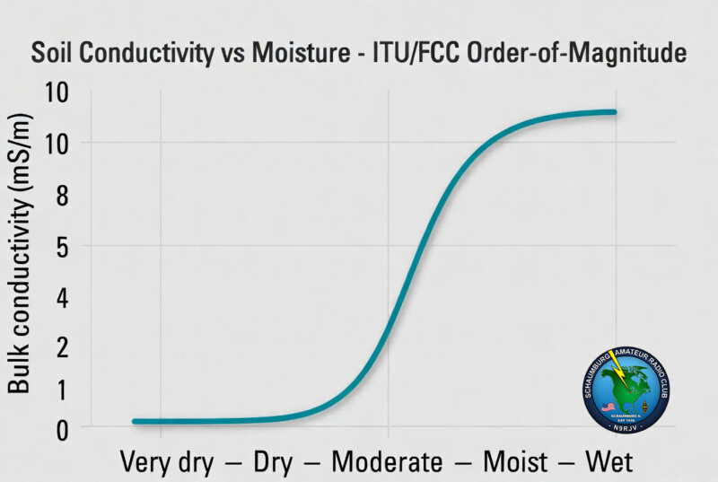
The reason this matters electrically is direct and large. FCC’s ground-wave references say U.S. ground conductivities typically span roughly 0.1 to 30 mS/m. ITU-R P.527/P.527-5 says moisture is the major factor controlling soil permittivity and conductivity and gives a useful order-of-magnitude example: loam may normally be around 10⁻² S/m, but when dried can fall to about 10⁻⁴ S/m. USDA/NRCS says the same thing in plainer language: wetter soil conducts better.
An illustrative engineering view looks like this:
Illustrative soil conductivity vs. relative wetness
Very dry Dry Moderate Moist Wet
10 9 8 7 6 5 4 3 2 1 0
Bulk conductivity, mS/m
(Order-of-magnitude synthesis from ITU, FCC, USDA/NRCS, and soil-EC literature)
This is not a site calibration; it is an order-of-magnitude synthesis from ITU, FCC, USDA/NRCS, and soil-EC literature showing the direction and approximate scale of change that can occur as moisture rises. Texture, salts, organic matter, and compaction can move a real site far above or below these points.
Grounding, radials, and the physics behind performance changes
ARRL’s grounding guidance is unusually clear on the central distinction: safety ground, lightning ground, and RF ground are not the same thing. A quarter-wave vertical needs an RF return path with low RF resistance; a ground rod helps only a little at RF and remains a high-RF-resistance connection compared with a proper radial system. ARRL’s verticals primer adds the other half of the picture: the vertical is effectively a dipole with half its structure “mirrored” in the counterpoise or ground system, and poor ground conductivity makes the classic joke true that a bad vertical “radiates equally poorly in all directions.”
In circuit terms, the important quantity is radiation efficiency:
η ≈ R_rad / (R_rad + R_loss)
ARRL’s modeling tutorial states this explicitly, and for short verticals the implication is severe: if the antenna’s radiation resistance is already low, then a few extra ohms of ground loss become a large fraction of the total input resistance. That is why short, loaded, or low-band verticals are much more sensitive to soil and radial quality than a better-behaved half-wave structure.
The near field around the base is where the damage happens. N6LF notes that most ground loss is concentrated within about half a wavelength of the base of the vertical. That does not mean every radial must be half a wavelength long; it means the first portion of the return-current region is the most valuable place to reduce loss. It is also why adding more modest-length radials near the base is often more productive than trying to install just a few very long wires.
Drying soil affects both loss and tuning. ITU says moisture changes both conductivity and permittivity. In N6LF’s elevated-radial analysis, the radial length needed for resonance at 3.65 MHz changed with soil characteristics, and a low dipole at 8 ft could resonate anywhere from roughly 64.5 to 66.4 ft depending on soil. In his 2009 measurements, he also noted that small changes in the system could vary with soil moisture and that observed measurements were run after periods of rain and after later drainage/drying. So a drying site can do three things at once: raise ground loss, shift resonance, and change feed impedance.
The most useful experimental ham evidence in the source set comes from N6LF’s QEX work on 40 m. With 33-foot radials on the ground, going from 4 to 8 to 16 to 32 radials improved field strength by roughly +2.26 dB, +3.76 dB, and +4.16 dB relative to the 4-radial baseline; he explicitly described the 4-radial case as “really flaky” and suitable only as an emergency measure. Separately, his Part 3 measurements found 64 radials on the ground at about +5.8 dB over the 4-radial ground baseline, while 4 elevated radials at 48 inches produced about +5.9 dB, which is effectively the same result for practical purposes.
That experimental result is the cleanest answer to the buried-vs-elevated question: many on-ground radials work, and a small number of properly resonant elevated radials can work just as well, especially where space is limited. But there is a catch. N6LF’s later elevated-radial analysis showed that with only a few radials, making them “too long” relative to the optimum can create a deep gain notch, even on the order of several dB, and can move the takeoff angle upward. In other words, sparse elevated radials must be treated as resonant antenna elements, not just “some wires that look about right.”
ARRL and secondary ARRL-hosted references in the source set also support several practical corollaries: surface or shallow-buried radials are preferred for ground-mounted verticals; poor soil requires more elevated-radial height for the same performance; and ground rods do not replace radials for RF return current.
Practical station guidance for Midwest EN operators
Radial and counterpoise choices
If you have room for a real ground system, the most robust HF choice in the Midwest EN region is still a ground-mounted vertical with many on-ground or shallow-buried radials. For 40–10 m, N6LF found that 32 radials of about 33 ft worked very well whether on the ground or elevated, which is a strong practical benchmark for multiband field and home installations. If you cannot lay that many wires, use 16–32 rather than stopping at 4–8 if at all possible.
If you cannot lay many ground radials, then do not half-commit to a poor earth return. Instead, switch strategies: use 4 resonant elevated radials at a genuine height above ground, or use a complete antenna structure such as a vertical dipole or other design that does not depend on earth-return RF current. ARRL explicitly notes that a “complete” antenna such as a dipole or ground plane does not require an RF ground in the same way, provided common-mode current is controlled with a choke.
| Configuration | Evidence-backed behavior | When to use | Main risk / caveat |
|---|---|---|---|
| 4 on-ground radials | Emergency-level baseline; N6LF called this “really flaky” | Portable, temporary, proof-of-concept | High ground loss; strong seasonal sensitivity |
| 8 on-ground radials | About +2.26 dB over 4-radial baseline on 40 m | Entry-level improvement | Still meaningfully lossy |
| 16 on-ground radials | About +3.76 dB over 4-radial baseline | Good practical minimum for many sites | Dry soil still hurts |
| 32 on-ground radials | About +4.16 dB over 4-radial baseline; worked very well 40–10 m in N6LF work | Strong home or semi-permanent installation | Labor and yard management |
| 64 on-ground radials | About +5.8 dB over 4-radial baseline | High-performance installation | More wire for diminishing returns |
| 4 elevated resonant radials | About +5.9 dB over 4-radial ground baseline, roughly matching 64 on-ground in N6LF’s 40 m test | Small lots, roof/deck edges, constrained sites | Must be resonant, symmetric, and properly elevated |
| Ground rod only | Helps little at RF; ARRL says RF resistance remains high | Safety/lightning system only | Not a substitute for RF counterpoise |
*Table values are synthesized from ARRL grounding guidance and N6LF’s QEX measurements.
What to expect as the soil dries
| Soil / moisture condition | Representative conductivity band | Likely antenna symptoms | Best operator response |
|---|---|---|---|
| Wet to moist | ~3 to 10+ mS/m | Lowest ground loss; tuning close to spring baseline | Record analyzer baseline; this is your reference state |
| Moderately dry | ~1 to 3 mS/m | Slight upward/downward resonance drift, more tuner work, weaker low-band reports | Add radials near base, verify choke, compare WSPR/PSK reports to wet baseline |
| Dry | ~0.3 to 1 mS/m | Noticeable efficiency loss on 80/40 m verticals, feedpoint resistance/reactance shift, “it tunes but is deaf/weak” complaints | Add 16–32 radials if possible, or convert to elevated resonant radials |
| Very dry / drought-stressed surface | ~0.1 to 0.3 mS/m or worse | Ground loss dominates short/loaded verticals; strongest seasonal performance drop | Temporary irrigation near base if practical, aggressive radial upgrade, consider vertical dipole or complete counterpoise design |
These conductivity bands are engineering approximations, not measured site values. They are based on the FCC/ITU/USDA ranges and on the fact that ITU’s loam example spans about 0.1 mS/m to 10 mS/m as soil dries or wets. The strongest practical impact will usually show first on low-band verticals and shorter loaded antennas because their loss budget is least forgiving.
Tuning and measurement
Use an antenna analyzer first and an SWR meter second. The analyzer tells you where resonance moved, whether feedpoint R and X changed, and whether the antenna became “easy to match but inefficient.” A shack SWR reading alone cannot tell you that; even ARRL licensing material reminds operators that a perfect 1:1 SWR does not guarantee an effective antenna.
For a rigorous Midwest EN seasonal workflow, build a wet-spring baseline and then compare it to late-summer dry-state measurements. Record at minimum: resonant frequency, (R), (X), SWR bandwidth, band/mode, transmit power, radial count, and soil condition. Then correlate those station measurements with PSKReporter or WSPRnet observations using the same band, power, mode, and time-of-day windows. A consistent drop in spots or in median path quality during dry periods, with the rig and schedule held constant, is strong circumstantial evidence that the ground system is the culprit.
If you want to test your safety/lightning grounding electrode, use a real ground-resistance tester rather than RF instruments. IEEE 81 is the governing measurement standard for ground resistance and potential gradients in earth. Clamp-on and fall-of-potential tools are the right electrical-domain instruments for this job. But be strict about the interpretation: that result tells you about the grounding electrode system, not the RF quality of your radial field. RF performance still has to be evaluated by feedpoint measurements and on-air field results.
Seasonal maintenance and dry-condition mitigation
For the EN Midwest climate, the highest-value maintenance is seasonal rather than one-time. After the wet spring, measure and log the antenna. Then repeat after prolonged dry periods, because that is when conductivity and permittivity shifts show up most strongly in real use. If the resonant point moves only a little but outgoing reports fall materially, the likely culprit is higher loss, not a catastrophic mismatch.
When dry conditions arrive, prioritize mitigation in this order:
- Add or densify radials, especially close to the base where most ground loss occurs.
- If space is limited, shift to properly resonant elevated radials instead of tolerating a sparse ground field.
- Verify that the feed line is not becoming part of the antenna by adding or improving a common-mode choke where appropriate.
- For temporary relief, wetting the soil near the base can help because soil conductivity rises with moisture and most loss is concentrated near the antenna base region.
- If the site is chronically poor, consider a complete counterpoise-based design such as a vertical dipole or other structure less dependent on earth conductivity.
Open questions and limitations
I did not establish a formal, authoritative geographic boundary for “Midwest EN,” because none of the reviewed official sources define one. I therefore used the user-specified interpretation and noted the alternate Maidenhead-grid meaning of “EN.”
I also did not quantify a separate, Midwest-specific 6-meter Sporadic-E climatology in this pass, because the strongest high-confidence recent sources I gathered were better on HF space weather, tropospheric VHF/UHF, and ground-system engineering than on real-time 6 m Es for this specific region. The VHF/UHF discussion above therefore emphasizes the tropospheric mechanisms that were well supported by the current source set.
Finally, the conductivity-versus-moisture plot and the recommended conductivity classes are engineering approximations, not a site survey. If you need a design-grade number for a specific property, the right next step is a local soil/ground-conductivity measurement or modeled estimate, plus a station-specific before/after validation with analyzer readings and on-air weak-signal reporting networks.