Field Measurements & Troubleshooting Flow
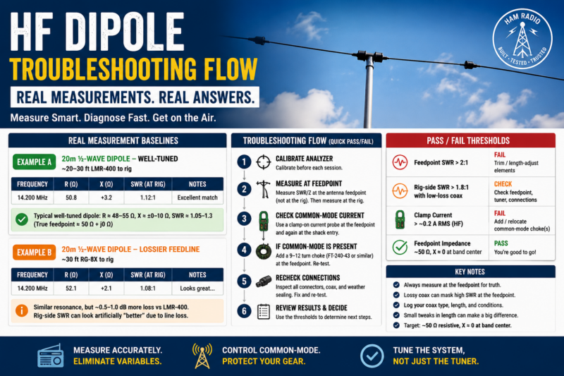
This quick-reference guide helps troubleshoot HF dipoles using real-world measurements, feed-line comparisons, and a practical field workflow.Shop‑Ready Measurement Examples (20m Half‑Wave Dipole)
|
Example |
Feedline | Rig‑Side R (Ω) | Rig‑Side X (Ω) | Rig‑Side SWR | Notes |
|---|---|---|---|---|---|
|
A Well |
20–30 ft LMR‑400 | ≈ 48–55 | ≈ ±0–10 | ≈ 1.05–1.30 | Feedpoint ≈ 50 + j0 Ω |
| B Lossier Line |
30 ft RG‑8X | Similar resonance | Similar | May appear “better” | Expect 0.5–1.0 dB more loss vs LMR‑400. Lossy coax can hide true SWR. |
Page Troubleshooting Flow
- Calibrate analyzer using open / short / load.
- Measure directly at the feedpoint first.
- Record R, X, and SWR at the operating frequency.
- Measure again at the rig with the installed feedline.
- Clamp a current probe at the feedpoint and shack entry.
- If common‑mode current is present, add a choke and re‑test.
- Inspect connectors, weatherproofing, and strain relief.
- Trim or length‑adjust elements to center resonance if needed.
HF Dipole Recommended Choke
Use a 9–12 turn FT‑240‑43 ferrite choke or equivalent at the feedpoint and/or shack entry to reduce common‑mode current on the coax shield.Pass / Fail Thresholds
- Feedpoint SWR > 2:1 → trim or length‑adjust the dipole elements.
- Rig‑side SWR > 1.8:1 with low‑loss coax → verify feedpoint mismatch.
- Clamp current > ~0.2 A RMS at shack entry → add or relocate choke(s).
- Lossy coax can make SWR readings appear better than reality.
Target values near band center: R ≈ 50 Ω and X ≈ 0 Ω.
HF Dipole Field Tips
- Document coax type and total feedline length.
- Keep the feedpoint centered and mechanically balanced.
- Weatherproof all outdoor connections.
- Use low‑loss coax whenever possible for accurate readings.
- Recheck measurements after each change.